Chris Donnelly
C++ Engine Developer (Systems) in Frankfurt Am Main, Germany
MSc Dissertation Project / University of Hull, 2016-17
A virtual reality painting application in room-scale, using customizable fuzzy sets, skeletal joint filtering, and search trees to paint in 3D using gestures.
Written in C++11, using Direct3D11, Kinect V2, Leap Motion (now UltraLeap), Oculus VR
Note: This document was written before Leap Motion became UltraLeap. All "Leap Motion" references refer to UltraLeap now
Inspired by Microsoft Hololens🗗, I chose the "Virtual Paintbrush" project for my MSc dissertation project at Hull. I wanted to create an application which could replicate some of the advantages of the Hololens (namely, more spatial awareness, and a connection between real-world movements and their digital representations by measuring the user body dimensions and positions and reflecting them in a matching virtual-world space, meaning the user height, actions and room-position are more accurately tracked than with current software).

The software would of course require a VR HMD, and sensors to detect the user (from body positions to extremities such as hands, fingers, etc). I decided to use consumer-grade hardware and accompanying APIs (Oculus Rift DK2🗗, a Leap Motion Controller🗗 and Microsoft Kinect V2🗗) to achieve this.
Main UI of application, body viewed from "scene" camera (full resolution image here)
live mirroring of the Oculus (each "eye" view) alongside a overview of the body view, plus all options in AntTweakbar
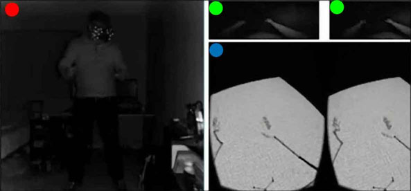
Live sensor feedback (red: kinect2 infrared / green: leap infrared / blue: oculus mirror)
The application is written in C++11, and is developed for Microsoft Windows 10 (as a Win32 app), and uses a bespoke entity-component system for rapid development. Further libraries and specifications:
Hardware used:
The application itself requires numerous major components (and subsystems) to manage the multiple APIs and data flow; these components can be divided up into the following:
This project is a quite complicated collection of systems, the application framework section will describe a higher-level overview of the application when running. Please refer to the list above for further detail into each component or system.
The application framework is a C++11 entity-component hybrid; entities are containers for components, which are processed by their respective systems (such as mesh data being acted upon by the rendering system).
The app uses Direct3D11 as a rendering system, and extends its usage to render to the Oculus HMD and the UI renderer post processing layer. This system allows rendering by passing a list of entities, a 'camera' (appropriate viewing parameters such as a view and projection matrix), and a given render target object.
Hardware body sensors (and their APIs) are managed by wrapper classes (see Sensors/APIs), with the main loop of the application polling the APIs/devices for new data, and when available storing the new data (and managing previous data with a 'dirty' flag). These wrappers function similarly, and are statically initialized, beginning their work only after a call to a given "Initialize" method. Polling is carried out by querying the wrapper, and if true, an encapsulated data 'packet' is obtained from the wrapper to be processed.
The application uses a scene paradigm, although only one scene is used in the application, more can be added to change functionality or interaction. The scenes register callbacks when loaded to be invoked upon windows events (resize, click, move, etc) to maintain logical responses from the scene. Exceptions to this are the forced termination of the app, and insertion or removal of selected USB hardware from the device map/tree (meaning a USB device has been plugged in and activated/removed and deactivated); this functionality is managed by the application code itself to manage the API wrappers.
Once internal and system messages are processed, the main loop invokes the scene logic (in this case, the processing of the sensors and their data, and acting as necessary). This logic uses one or more User Body objects (the app intends only one, but multiple bodies can be overlaid, reading from the same body, highlighting different joint filtering techniques) to read, store and interpret the data as three-dimensional geometry, and store the information as joints.
The joints read are filtered (based on their type), and so can be processed to the geometry entities, to represent the scene. Also, the positions and states of the hands are compared against existing values (which are in an editable text file) to ascertain each bone position, in turn leading to each finger position, which in turn gives an overall hand position, and in turn both hands form a gesture or action.
The gesture painting class takes these gestures and actions, and executes the necessary actions (such as painting lines, ribbons, tubes, saving files, changing colours)
A key part of any body-reading project is the joint; a camera-space (where sensor is origin to its LCS) position representing a recognised point on the human body, supplied with its own properties such as biological measurement, rotation, etc. In the scope of this project, the location (and in the case of the UserSkeleton, rotation) data are mainly used to calculate joints, limbs, and therefore a body. Joints in this project are divided into two classes: the KinectV2Joint and the LeapJoint, representing detected body and hand joints respectively.
Joint classes are derived from the base/parent class based on the desired smoothing technique (see Joint Smoothing).
Two elements require consideration when using body detection devices and software; sampling rate (the rate at which new joint data is produced) and noise (irregularities in the data, producing inaccurate joint positions). Sampling rates are shown below:
| Device | Data rate | Frame Time | Notes |
|---|---|---|---|
| Kinect2 (Body) | 30hz | ≈ 33.3ms | ≈ 60ms processing delay |
| Leap Motion | ≥ 50hz | ≥ 20ms | Adaptive rate |
To compensate for lower sampling frequencies or data noise (both of which represent the real data inaccurately, causing negative effects such as stuttering or overshot), smoothing or interpolation on the data would be needed.
The filtered joint classes are derived from the abstract base (FilteredJoint) to perform no smoothing. Each joint maintains its own history and parameters (allowing custom smoothing paramaters on a per-joint basis, although implementing differnt smoothing techniques per-joint was not fully implemented). This also enables a combination of multiple smoothing techniques within a given user body (areas with low confidence may require different smoothing parameters or algorithms).
Techniques implemented are:
| Joint Type | Smoothing technique |
|---|---|
| PassthroughJoint | None (raw/passthrough with only confidence checking) |
| WeightedAvgJoint | Weighted Average (customizable parameters) |
| DoubleExpJoint | Holt Double Exponential (customizable parameters) |
The application allows the user to dynamically change the joint types (and therefore the smoothing technique) at run-time via the UI.
Each technique provides its own tradeoffs (providing filtered movement or reducing errors, at a cost of latency or accuracy):
| Technique | Gain | Loss |
|---|---|---|
| Passthrough | Minimal latency | No error reduction (outside of API) |
| Weighted Average | Heavy smoothing | Higher latency, best for linear movements |
| Double Exponential | Lighter smoothing, jitter reduction | Some latency, requires more tuning |
Other tradeoffs do apply; these are most important to the context of the project
Futher research is needed to provide a definitve answer as to the best combination of smoothing techniques and parameters; however the implementation allows output of all positions (per-frame, per-body) from each body to analyse positional differences over time for more statistical analysis, as well as rendering multiple filtered bodies overlaid to provide a complementary visual comparison analysis.
The joint reader classes are used to request the 'packets' (or frames) of sensor data from the appropriate API (a slight decoupling). Kinect2 and Leap APIs are queried for their new data and (if available), the readers retrieve the frame object, packing the data into a container, and unpacking it into the appropriate target location. These essentially manage packet/frame requests of data from the API.
Note: The UserSkeleton and UserHands classes use Joint Readers to access new data frames.
The UserBody class manages the virtual representation of the user (the avatar) as a whole, and contains one UserSkeleton and two UserHand classes, representing all detectable portions of a single body. The UserBody is updated as part of the current scene (or logic) loop, in turn passing a request to update the component skeleton and hand classes.
The UserSkeleton class represents the detected body excluding the hands (although does include the wrists, or carpals with a joint), which is referred to in this project as the skeleton (semantics notwithstanding). Managing the data from the KinectV2 sensor (obtained as data packets from the KinectV2API), the UserSkeleton manages entities for joints and 'limbs' (connecting geometry between joints), from creation to updating, keeping the the body representation up-to-date to the latest available Kinect body frame.
Any joints (and therefore limbs) which are not detected with confidence above a supplied threshold (set/obtained through the KinectV2API) are displayed with either an estimated state from the API (if supplied), or not updated (if data is not supplied), either way leading to some jitter/noise (see Joint Smoothing for more details on this). Either way, the joints and/or limbs are displayed using a defined material property (in this case: Red, 50% opacity) to visually indicate low confidence.
Like the UserSkeleton class, the UserHand class manages entities and data in the domain of the hand (finger joints, bones, etc). Entities representing finger bones (like the limbs) and joints ( which are gathered from the endpoints of bones in the Leap Motion data) are created by each UserHands (the body has one per real detectable hand), and the entities are updated with new data. As with UserSkeleton, the joints or bones which are low confidence are given visual indicators in the form of a different material property. Due to a higher data framerate/sampling frequency with the Leap Motion Controller/API and the precision of the sensor working to [claimed] fractions of millimetres, smoothing wasn't applied to the hand data after testing. hand joints
Note: The UserHand entities are set as children (and therefore child transformations) of the exposable UserSkeleton wrist entities; this attaches them to the wrist as a hand would normally attach, with a customizable three-dimensional offset vector known as the carpal offset to compensate for wrist bones, moving the hand away from the wrist to a desired scale.
Good Question. While the Kinect does 'see' the head as a joint location with an approximate quaternion for rotation, more detail is needed for rendering to the Oculus Rift HMD. The Oculus SDK does provide a means of accessing the orientation information of the HMD (namely, the tilt of the user's head, looking direction, etc), but the location is often approximated as the sensor (a small IR camera) may not see the floor clearly (at the time of implementation, v1.19 --the version used-- was often found by users to report moving discrepancies of 50mm/1.9" up to 200mm/7.8" in the value of the height of the HMD from the floor). A hybrid approach was used to ensure the head would in accurately located and temporally correct (fluctuations would be unacceptable). To do this, The reading from the Kinect would be used for the location of the head, but the various rotations of the head would be provided by the Oculus API (namely the OVRAPI). This approach provided an accurate representation of the head (requiring the sensors were aligned correctly; see additional notes for more information).
Some smoothing was still necessary due to the two sensors having different data frame rates and measurement fidelity, so a weighted average filter (with a smaller history size and nonlinear decreasing weight values) was applied to the translation values of the head to smooth out physical translations of the head.
But why is there no UserHead class? There was little need to create more than a derived VR-compatible camera object to mimic the user's viewing parameters; a specialised camera class to work with the Oculus SDK and work as the user's eyes.
Output to the screen, UI layer of the screen and Oculus HMD is achieved using Direct3D 11.0 as a general-purpose renderer. The functionality of the renderer was extended beyond a regular Win32 application to accomodate the Oculus HMD.
The renderer is statically instanciated to perform its rendering duties, and while static classes are constructed before the main entry point of the application, the DXRenderer takes no action until its method "Initialize" is invoked. When this happens, D3D resources are created for rendering, offscreen buffers (depth, stencil, render target, etc) and render modes (structures such as stencil types, rasterizer modes, etc) are created and stored internally. The renderer is also invoked during the program's configuration phase to initialize data buffers (textures) for specified material objects and geometric data (supplied by a procedural geometry generator subsystem).
The OVRAPI will request from the DXRenderer that buffers be created as render targets and depth/stencil buffers (each eye viewport in the HMD is allocated two RenderTarget buffers as part of an libovr-specific swapchain object, and one depth/stencil buffer for rendering - four render targets and views, and two depth stencil buffers). Of course, on shutting down the application, the OVR resources must be released alongside the main resources, these objects are stored within the OVRAPI and will be destroyed by the OVRAPI when required.
The rendering system is designed to recieve a list of entities; those with model components or material properties etc, are taken for rnder processing. The renderable entities have their transformation information extracted, and the renderer sets the Direct3D states to match the requirements of the list of components that are the entity (such as extracting the material information for texturing, the designated shader(s), the rasterizer mode etc), setting shader parameters appropriately. The entity's associated mesh component is then rendered. The de-coupled mesh and materials are rendered zero or many times (with potentially different transformations and materials) throughout the rendering process, keeping the option of hardware instancing open for future optimisations, and the memory footprint low for mesh data and potentially reducing GPU cache misses via extensive loads of multiple instances of the same data.
The system has only one renderer; the DXRenderer performs all rendering. Device or Window handles are passed alongside appropriate viewing parameters to render correctly to each output device (or layer). This allows the renderer to remain multi-purpose while not being fully abstract, and avoids the necessity for extra setup overhead or more context switches.
The Window renderer refers to the DXRenderer operating in the context of the render targets, views and resources allocated to a given Win32 Window via its HWND handle. The render target is set to the resources and swapchain tied to the HWND, and internal states are set accordingly. The list of entities is processed for rendering by the renderer, and the output image created as normal. For window rendering the scene, a 'scene' camera is used (a view and projection matrix set to the parameters of viewing the scene). This camera is passed alongside the entities, and the view/projection matrices are extracted for rendering as a scene camera.
The Oculus renderer is a slightly more complex beast than the Window renderer, as it must request rendering two times (obviously, one per eye view) with slightly different viewing parameters to accurately allow rendering from the location of each eye (the HMD/API provides a reading for IPD: interpupillary distance -- effectively the distance betweeen the pupils when looking straight ahead). For the HMD, an 'OVRCamera' is used, derived from a scene camera to allow more control by supplying the view/projection matrix from the Oculus API (HMDs models have varying FOVs and resolutions resulting in a different projection matrix for each HMD; Oculus documentation recommends always using the API to retrieve the projection data).
The UI overlays in the app (such as live camera data and Oculus mirror) are only rendered to the window. The UI renderer is designed to use the DXRenderer to render elements to the same buffer as the scene render, using a 'UICamera' -- an orthographic projection matrix set to the window's buffer size and identity view matrix.
UI Overlay elements (highlighted blue)
As you can see above, the app uses AntTweakBar (left) to enable tweaking and show statistics; the bar is created by the scene, but the rendering call is managed by the UIRenderer. The bar uses opacity, so it is rendered last.
UIElement objects (geometry whose texture data is live sensor camera data or mirror renders - right side of above image) create and set entities for rendering (quads with updatable texture data); these entities are stored internally in a cache-friendly list inside the UIRenderer, and passed as the renderable entities for rendering (instead of the entire scene). A small optimisation here is to render the UIElement objects first (depth/stencil enabled), and then the scene, removing overdraw for those sections of screen when rendering the scene (effectively the inverse painter's algorithm).
The project (rather obviously) makes use of hardware such as a Leap Motion Controller, Kinect V2 and Oculus DK2 (with sensor); each item requires its own software to control and access readings for these hardware items. Each API functionality is wrapped in a statically instanciated wrapper class (KinectV2API, OVRAPI, LeapAPI for Kinect V2, Oculus and Leap Motion respectively). Since statically insanticiated classes are constructed at global scope and before the entry point of the program, the API wrappers do not initialize and create resources until the initialize method is called. This allows the application to prepare any necessary information before the API begins (such as needed handles and events, etc). Each API is gracefully closed down (and resources released or deleted as necessary) via the Shutdown method when the application closes itself down or is closed.
Each API has an Update method, which is called to retrieve the latest state of the APi and hardware, and check for new data (if the API/device is functioning - if not, it shuts down the wrapper ready to be re-initialized by the main application logic loop). Any new data is stored internally, and a flag for new "clean" data is set.
The Oculus wrapper encapsulates the libovr (Oculus SDK) functionality and state objects to provide a simple interface to address the API and hardware. The API creates HMD and view data types and accesses the oculus device (and sensor) via a stored session ADT. Rendering objects and states for the HMD are stored in the Oculus Renderer class, but the requests to create these objects are made via the Window Renderer/DXRenderer.
The API also had a method to enable the UIRenderer, to render the OVR output (mirror) to a specified material, which is in turn used by a UIElement, meaning the texture of a UIElement is updated to the newest mirror texture available.
The Kinect 2 API manages the Kinect2 SDK functionality and internal objects, retrieving body and infrared frames (although more frame types are available).
Frames of body data and infrared captures are stored internally, ready to be accessed by JointReaders or copied to material data, when they are marked as 'dirty' or used. Furthermore, sensor details, such as percieved height from a floor, framerate and body confidence are accessed (or calculated by the wrapper), and ready to be passed to other systems if needed.
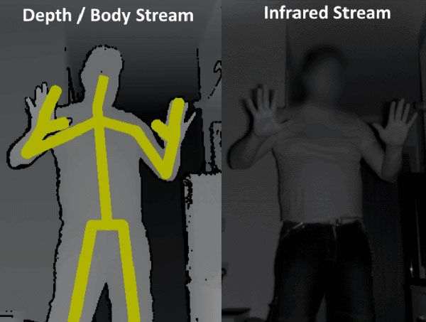
Kinect 2 Depth stream (left) and Infrared stream (right)
While specific user-tracking is implemented in the Kinect API, it is not implemented in the project; the user is assumed and advise to be the closest user to the sensor, and in optimal conditions, should be the only person in view of the Kinect.
Like the Oculus API wrapper, the KinectV2API has a method to copy captured frame data (infrared in this case) to a specified material object, to be used by the UIRenderer and UIElements.
The Leap API Wrapper (LeapAPI) encapsulates functions and objects from the Leap SDK, working in the same way to the Oculus and Kinect API wrappers.
A major difference to the other APIs is that data frames are split into two body frame types and two camera image types; left and right. The data frames from this sensor vary from zero upward, sensing no hands, one hand, two, or more. This requires two polling options for data and image frames: left and right. The API wrapper is queried for both hands in one call, but may not necessarily return two hands as desired (or the two intended).
On update, the API queries the current frame for the first (closest to sensor) left hand available, then the first (closest) right hand available. While tracking errors are possible for multiple users in the scene, the sensor is mounted to the HMD, and is therefore most likely to return the user's own hands (although it is recommended in the documentation to use a safe and clear area free of other people for optimal detection). Detected hands are stored locally ready for the next query to read them (with a flag raised to show new/fresh data). Hand data is passed as joint packets, while the API wrapper implements the same technique as the other APIs in the project; it can copy image data to a specific material object for UI rendering.
After all the application, sensor, API and render management work is functioning, the program needs to be able to understand when the user's body is in a particular pre-defined state to act upon (such as a 'drawing' pose). Hard-coding values is a bad practice for most programmers, but makes for bigger problems when each user has different capabilities and measurements for their body and hands. Clearly, the developer's measurements (mine) won't match other user measurements or abilities (other users may have more or less ability of movement), but completely abstract values are no use either; the answer to measure the positions of fingers on a hand, or position of a body is to measure it agains itself, or at least agains its own standard measurements. To this end, the hand poses would measure the finger bone positions relative to their neighbours and the general palm normal and orthonormal basis vectors.
While right-handed, I thought it best to implement handedness to allow run-time switching between left and right-handed operating modes. The project does not refer to left or right hands when processing hand gestures, but uses the terms dominant and non-dominant, which refers to the UI selection on the main screen (choice of left/right). All pose enumeration and action processing uses arguments of a dominant and non-dominant hand to abstract usage to customizable working paramaters.
Painting in the application does not require any physical objects (stylii, remote devices, etc) to 'paint'; the application parses the current hand positions into actions to carry out, and both hand pose and action are customizable through a series of human-readable data (mostly) read by the application on initialization. In short, these files represent what constitutes a finger's pose, and which finger poses constitute a hand's pose, and which two hand poses constitute a gesture.
Think of the config files specifying a program command (such as paint, save, etc) from the finger (phalange) bones up to two hands:
The GestureAction is made of two HandPose values, which is made of five FingerPose values
The FingerPose is an enumerated value which defines the state of one finger:
| Fingerpose Enum | Meaning |
|---|---|
| STRAIGHT | Finger is held straight |
| RELAXED | Finger is slightly curved, a relaxed state |
| CURVED | Finger is deliberately curved/bent (more than relaxed) |
| CLOSED | Finger is heavily curved into a fist state |
| NONE | Unreadable / error state |
The HandPose is an enumerated value which defines the state of one hand (such as a fist, or pointing):
| HandPose Enum | Meaning |
|---|---|
| OPEN | Open hand with straight fingers/thumb along the palm x/z basis |
| OPENGRAB | Open hand, curved fingers/thumb as if holding a medium/large ball |
| FIST | Closed hand with fully curled digits. A fist |
| RELAXED | Open hand with very light curvature to fingers/thumb |
| POINTINDEX | Closed fist, thumb fully bent, straight index finger |
| POINTMIDDLE | Closed fist, thumb fully bent, straight middle finger |
| POINTRING | Closed fist, thumb fully bent, straight ring finger |
| POINTPINKY | Closed fist, thumb fully bent, straight little or "pinky" finger |
| THUMBUP | Closed fist, straight thumb |
| INDEXTHUMBL | Straight index finger, straight thumb, all other fingers in a fist |
| INDEXMIDDLEV | Index and Middle finger straight, all other digits in a fist |
| PINCH | Fist, with Index and Thumb curved and touching at the tips |
| THREECURVED | "Pinch" action (above) including middle finger |
The GestureAction is an enumerated type which represents two HandPose values (such as two fists, one open hand and one pointing with index finger) they are editable values stored in the configuration files, which tie two HandPose values to an internal program action (non-exhaustively; more combinations/poses are easy to add to the framework).
The current GestureAction command values are as follows:
| Enum | Description | Action taken |
|---|---|---|
| NONE | No GestureAction | None |
| INVALID | Both hands are out of the sensor's view | None |
| PAINT | Paint | Start/continue painting (depends on dominant hand) |
| GRAB | Translate/Rotate last painted geometry | Unimplemented |
| LOAD | Load a previously saved .OBJ scene | Partially implemented |
| SAVE | Save the current 'painting'/scene to .OBJ file | None |
| MENU | Show choosable options | Change paint colour/material |
| OK | Confirm decision / Stop painting | Stop painting ("close" geometry) |
Mappings between GestureAction and handposes (dominand and non-dominant) are made in the config files, as readable text values.
How does the app determine these poses and values? The config files contain pre-averaged values to classify the poses of a finger as straight, curved, closed, etc. These values are compared to the signed angle between the z-basis of each bone (longitudinal axis; the line running 'through' the centre of the bone tip to tip). The accumulated angles represents the overall curvature value of the finger (every set of two neighbouring bones in the finger are compared and the value is added to a running total). There still can be some issues on borderline cases, where fluctuation can occur between states, so fuzzy set membership functions are used to define the state of the finger's curvature:
The implemented membership functions (top-bottom: General Bell, Trapezoid, Triangle)
The configuration allows the user to choose which membership functions to apply (choice of triangle, trapezoidal or general bell) to the finger data. The MemberFuncs are derived from a base class, and can be swapped out easily, or extended to more complex functions (gaussian, etc). Five membership functions are prepared from file data (assigned to NONE, STRAIGHT, RELAXED, CURVED and CLOSED), and finger curvature is passed to the collection of functions, with the highest membership value being the successful FingerPose candidate to return (cases of no membership at all return NONE as an error catch).
The value of finger curvature (or x) = 0.81 gives a highest membership value for the orange function (CURVED)
All detected (and valid) fingers are tested this way to ascertain all finger poses. Assuming one or both hands are detected and valid, we have two sets of five FingerPose values (if only one hand, only five are tested, if no hands, no values, and processing exits for this loop). Since the finger poses are now calculated, a HandPose needs to be calculated from this data.
The config files contain yet more helpful and editable data to do this: Pose tree data - this is used to build a tree to search for poses. An example line:
POINTINDEX 2 3 0 1 2 3 2 3 2 3
Using the format:
[GestureAction] [a][b] [c][d] [e][f] [g][h] [i][j]
The [GestureAction] being defined is a string literal; in this case the line is defining the tree entries for the POINTINDEX HandPose (closed fist, straightened index). The integer values defined in the example are interpreted as FingerPose enums (0=STRAIGHT, 1=RELAXED, 2=CURVED, 3=CLOSED, 4=NONE). There are five pairs of FingerPose here; each pair represents the lower and upper bounds of FingerPose that a finger can be evaluated to while being considered valid for this HandPose.
That's quite a mouthful, and can be more easily explained by working through the example line. Here's what it says in [slightly more] plain English
POINTINDEX	2 3	0 1    2 3    2 3    2 3

- I'm defining the HandPose "POINTINDEX"
- The thumb pose should be in either position CURVED or CLOSED (2-3)
- The index finger pose should be in position STRAIGHT or RELAXED (0-1)
- The middle finger pose should be in position CURVED or CLOSED (2-3)
- The ring finger pose should be in the position CURVED or CLOSED (2-3)
- The little finger pose should be in the position CURVED or CLOSED (2-3)
These are ranges of FingerPose enums to consider.
Each HandPose is defined in the file in the same way using pose tree data:
OPEN			0 0    0 1    0 1    0 1    0 1
OPENGRAB		1 1    1 1    1 1    1 1    1 1
FIST			2 3    2 3    2 3    2 3    2 3
RELAXED			1 2    0 1    0 1    0 1    0 1
POINTINDEX		2 3    0 1    2 3    2 3    2 3
POINTMIDDLE		1 3    2 3    0 0    2 3    2 3
POINTRING		2 3    2 3    2 3    0 0    2 3
POINTPINKY		2 3    2 3    2 3    2 3    0 0
THUMBUP			0 0    3 3    3 3    3 3    3 3
INDEXTHUMBL		0 0    0 0    3 3    3 3    3 3
INDEXPINKY		3 0    0 0    3 3    3 3    0 0
INDEXMIDDLEV		2 3    0 0    0 0    2 3    2 3
PINCH			0 1    1 2    2 3    2 3    2 3
THREECURVED		2 2    2 2    1 1    3 3    3 3
The data is built into a custom sparse N-ary tree for searching. The N-Ary tree is a maximum depth of 5, as users are expected to have 5 fingers per hand (future considerations are to customize this for other users). Each node in the tree has N branches, representing each enumerated FingerPose. Multiple nodes are created for each permutation in the ranged FingerPose data.
A simplified pose tree
As the FingerPose values are used to search the tree (starting with the thumb, working to the pinky), the search will provide one of two possibilities; the FingerPoses match defined HandPose tree data, and lead to the defined pose (all FingerPoses match the critera for POINTINDEX, so POINTINDEX is returned), or the route through the tree stops because there is no predefined route made by the pose tree data, meaning the HandPose is NONE - an invalid or non-actionable result. Every dead end experienced before maximum depth is a NO POSE situation (or for incorrectly defined data, an incomplete pose, which may cause undefined behaviour).
Now the application has now searched a user-editable (well, indirectly) tree structure to retrieve a HandPose, using FingerPose data. The application knows the HandPose of each hand. These HandPoses are passed to the GestureController class (see Timing poses and gestures for further information) to be processed and passed up the 'chain'.
Once more the configuration files play a role; they define the dominant and non-dominant HandPoses which create GestureActions (for example, an open hand and a fist means 'save', etc). This allows user customization to set which gestures perform which internal commands. The values in the file are hashed to create a key, tied to the GestureAction in an unordered map. The GestureController searches the map for the dominant and non-dominant HandPoses (hashed together) for a corresponding GestureAction. If one is found, this is the new GestureAction to be carried out; if not, no GestureAction exists for this combination, and no action needs to be carried out by the app.
The GestureController class is the first class to recieve the two HandPose values for dominant and non-dominant; it has two purposes in the application - first is to find matching GestureActions for the current HandPoses from the specified values in the data files (or return a state of 'no gestureaction'), and secondly to perform timing control of the GestureActions.
The file data reads in this format:
[GestureAction] [Dominant HandPose] [Non-Dominant HandPose]
The data:
PAINT			PINCH			NONE
PAINT			PINCH			INVALID
MENU			NONE			THUMBUP
MENU			INVALID			THUMBUP
So for the top two lines, we know that to PAINT, the app will look for a PINCH pose in the dominant hand, and NONE in the nondominant hand. Note the line is copied below and includes INVALID; this ensures that both NONE and INVALID (out of view, or unreadable) are acceptable values for the non-dominant hand. The further examples work exactly the same, producing a MENU action if the non-dominant hand is THUMBUP and the dominant hand is either NONE or INVALID.
Timing - the second duty of the GestureController, is essential to maintain program performance. Cooldown values are applied to GestureActions to ensure that actions are not repeated every frame (unless necessary), such as SAVE - if the user performs the SAVE gesture, the application would save the scene to a file anything up to 90 times in one second - not best for performance.
The controller also has a complementary class called a GestureFilter, which conversely applies a 'warm-up' value to each GestureAction - ensuring no split-second fluctuation of GestureActions (for example, they must be the same value for 0.15 seconds to ensure no fluctuation between similar poses). These values help to ensure that gestures are deliberate and smooth.
Interestingly, the cooldown can also be applied to the PAINT GestureAction, effectively setting a 'sampling rate' or 'resolution' for the act of painting (a value of 0.1 seconds cooldown means 10 samples per second, giving a higher mesh/painting resolution than sampling at 0.25).
The GestureActor class is passed HandPose, GestureAction, and skeletal/hand coordinate data from the GestureController (this data is filtered by time, and not necessarily passed every frame; see Timing poses and gestures). When the GestureActor recieves this information, it acts - it carries out the GestureAction as a command, using the hand/pose/skeletal data available.
When the GestureActor carries out a PAINT command, it uses mappings from the config files to paint in the appropriate style (such as a pinch movement producing a thinner line, while a grab movemend produces larger, wider geometry). These internal modes are enumerated into PAINT_LINE, PAINT_MEDIUM, PAINT_TUBE, etc (and are extendable). An external entity list in the entity manager is created for this application to add and control 'painted' entities (since E-C systems maintain complete abstraction from what any entity is or contains, entities need to be arranged to avoid mixing permanent application geometry and painted scenes). This list is controllable by the application (all entities can be removed from the 'paint' list by pressing the space bar to 'start new'). This list is processed into file when the SAVE action is executed, and data from file is loaded into this list on a LOAD action.
An extra list of geometry is maintained to create mesh data at run-time; to create the painted mesh. This is partially offline, and not incrementally created, to minimise vertex buffer update costs, but referenced geometry (spheres, etc) is used to represent the geometry until its final form is build when the user is finished painting the current object (the current painting operation is stopped by the action being NONE or changed). The entities showing the temporary geometry are removed, and replaced with the real geometry (as an entity, with all transform operations available).
The main idea behind the application can be considered for further development, such as using multiple kinect sensors or natural UI software, or implementing a virtual environment where the full user body is realized for more realistic interaction with virtual objects and spatial awareness.
Proper sensor placement is essential; the Leap controller has a 3D custom-printed mount to hold in place on the front of the Oculus DK2 (although an official one is also available), it is necessary to keep this level, and steadily mounted. Options exist in the Leap software to detect orientation, but ensuring the sensor is the correct way up will remove this extra work. Also, any wires between the sensor and HMD should be tied back.
The Oculus IR ('constellation') sensor must be placed vertically above the Kinect V2 - otherwise, Y-rotation of the head will occur since the two sensor locations differ.
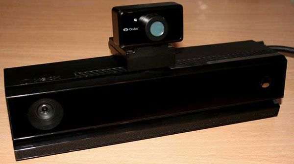
Setup for the KinectV2 and Constellation sensor
The system setup working under lab conditions (note the constellation sensor aligns with the Kinect V2):
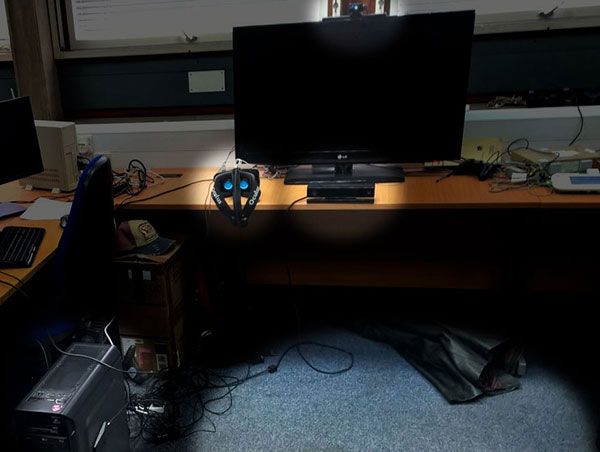
Lab setup for testing
As in the lab conditions photo above, the project requires the sensors align vertically, the hardware is connected by USB3.0 (Oculus, Leap and Kinect), and the user has a minimum of 2m × 5m physical space (uninterrupted) to operate from the Kinect V2 and constellation sensors.


